Power factor controller 6, 12 step – multicomp
Overview
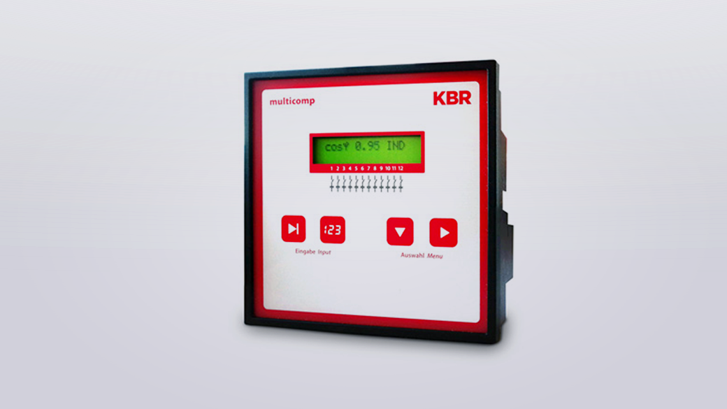
ใช้สำหรับควบคุมการทำงานของ Capacitor ให้ได้ค่า Power Factor ตามที่ต้องการ The microcontroller-controlled multicomp F144-3 records all network data relevant to the control of small systems via A/D transformer inputs. After calculating the required compensation power to achieve the desired target cos φ, the available capacitor stages are automatically switched on or off with a few switching operations. Programming is menu-assisted and is performed with two buttons. System-specific values are stored in a non-volatile memory. Each stage can be switched individually via the built-in manual-0-automatic function.
Product detail
- Detecting and compensating for the missing compensation power in case of recovery into the energy provider network
- Rapid compensation with few switching operation
- Display with two-line LC display, stage status an recovery
- Manual-0-automatic switch separately programmable for each stage
- Integrated temperature measurement
DEVICE TYPE
multicomp F144-xxx-3 Reactive power controller
| 1 | multicomp F144-xxx-6RO Reactive power controller with 6 relay outputs for the operation of detuned and undetuned PFC systems |
| 2 | multicomp F144-xxx-12RO Reactive power controller with 12 relay outputs for the operation of detuned and undetuned PFC systems |
| 3 | multicomp F144-xxx-6DO Reactive power controller, 6 optocoupler outputs for dynamic thyristor modules |
| 4 | multicomp F144-xxx-12DO Reactive power controller, 12 optocoupler outputs for dynamic thyristor modules |
| 5 | multicomp F144-xxx-6DO6RO Reactive power controller works with hybrid switching, 6 relay- and 6 optocoupler outputs |
| Switching stages | ||
|---|---|---|
| Relay outputs; 250 VA per output; 250 V AC: 50 / 60 Hz: [ 1 ] 6 [ 2 ] 12 [ 3 ] 6 Optocoupler outputs [ 4 ] 12 Optocoupler outputs [ 5 ] 6 Relay- und 6 Optocoupler outputs | ||
| Power per stage [ kvar ] programmable: | 0 to 999.9 kVar cap. | |
| Discharge times programmable: | 0 … 900 sec. | |
| Manual 0 automatic switch | status display: | Standard | Standard | |
| Learning function for automatic programming by induced current measurement (requirement: transformer fitted into the cable to the compensation unit) | via main current transformer | |
| Rotary field and phase allocation programmable | Standard | |
| Switching performance | ||
| Self-optimizing | Circular switching of equal stages: | Standard | – | |
| Special switching functions for | Multiple series connection | |
| Switch-off limit for low load operation: | programmable | |
| Monitoring functions | ||
| No-voltage trigger: | Standard | |
| Overcurrent switch-off (only in connection with induced current measurement) | – | |
| Overvoltage switch-off | fixed | |
| Excess current switch-off (only in connection with induced current measurement): | – | |
| Overvoltage switch-off: | fixed | |
| Temperature measurement and monitoring with fan control and emergency shut-down: | Standard | |
| Harmonics monitoring with alarm message and emergency shut-down | additional displays: | Standard | Voltage: KF – U, 3rd – 13th harmonic | |
| Error messages programmable: | Standard | |
| Target cos φ monitoring; alarm if unreachable: | Standard | |
| Switching operation monitoring with display per stage: | Standard | |
| Controller status display (over / undercompensation): | Standard | |
| Special operating mode | ||
| Thyristor fast circuit breaker (optocoupler outputs): | [ 3 ], [ 4 ], [ 5 ] | |
| Single-phase compensation | – | |
| Displays | ||
| Display type: | LCD | |
| Measuring parameters (RMS values | RMS): | U PH-N , U PH-PH , cos φ, f network , I main , Stotal, Qtotal, Ptotal , Q total demand, temp. | |
| Operating time display: | – | |
| Measuring | ||
| Measurement accuracy: Voltage | current | power | 0,5% | 0,5% | 1% | |
| Update speed: | 20ms | |
| Single phase measurement (4Q): | Phase-phase or phase-neutral | |
| 3-phase measurement | – | |
| 4-quadrant operation* | Standard | |
| Memory | ||
| Long-term memory: | – | – |
| Password protection | ||
| With digit code: | Standard | |
| Inputs | ||
| Voltage path: | Low-voltage; direct measurement | 30 V … 690 V … 790 V AC 50/60 Hz |
| Medium voltage | 1 V … 99.9 kV programmable | |
| Current path: | Main current transformer: | 1 x 0.15 A … 5 A … 6 A AC |
| Induced current transformer: | – | |
| Frequency range: | 40 to 70 Hz | |
| 2. Target value cos φ2 | Automatic switchover in case of energy recovery | to cos φ = 1 |
| Outputs | ||
| Additional relay outputs: | Standard | |
| error message relay/fan relay: | error message relay | |
| Interfaces | ||
| Serial interface with KBR eBus protocol: | – | |
| Modbus: | Modbus RTU | |
| Power supply | ||
| Operating voltage: | 85 – 265 V AC / DC | |
| frequency: | 50 – 60 Hz | |
| power consumption: | max. 15 VA, 9 W | |
| Dimensions | ||
| Switchboard installation: | Housing (H x W x D) | 144 x 144 x 60 mm |
| Switchboard cutout (H x W) | 138 x 138 mm |